



How Do You Verify Connector Solder Quality and Terminal Alignment Non-Destructively? On-Site Validation of Wahfei Technology HF-S90 and HF-S100 with a U.S. Customer
- Pubdate 2026-09-29
Industrial connectors are exposed to two typical quality problems: whether the internal solder joint is sound, and whether the terminals stay centered and aligned after overmolding. Both occur inside the part, where conventional inspection cannot reach. A U.S. customer recently visited Wahfei Technology with connector samples; based on the inspection requirement, our sales manager recommended the HF-S90 and the HF-S100, two micro-focus X-ray inspection systems, and validated both on the spot. This article documents the complete inspection, validation and selection process for the reference of companies with similar requirements.
1. The Inspection Need: Two Invisible Quality Risks
The customer’s samples are industrial connector parts. After the metal terminals are welded to cables, it is processed via encapsulation molding technology. Its quality control focuses on two core issues:
Solder joint integrity: the weld between terminal and cable is fully enclosed in Material, so cold joints, insufficient solder, voids in the weld and similar defects cannot be identified from the outside. A poor joint shows up as increased contact resistance and reduced current-carrying capacity, and under vibration or temperature rise it may develop into an open-circuit failure.
Terminal alignment after overmolding: during encapsulation, maybe push the terminals out of position. Once a terminal deviates from its designed position, the consequences range from poor mating and unreliable contact to assembly interference and batch scrap. Because the molded body is opaque, the actual position of the terminals cannot be confirmed by visual inspection after forming.
These two problems share one characteristic: the defect lies inside the molded body, is created during processing, and only surfaces at the end of the line. Destructive cross-sectioning can reveal the interior, but at the cost of destroying the sample: full inspection is impossible, and the section plane is a matter of chance. To confirm the internal condition without damaging the product, X-ray transmission inspection is the established non-destructive method in the industry.
2. Inspection Principle: Micro-Focus X-Ray Transmission Imaging
As X-rays pass through a sample, materials of different density and thickness attenuate the beam to different degrees, and the detector converts the transmitted radiation into a grayscale image: metal terminals, solder and other high-density areas attenuate strongly and appear dark, while the molding compound attenuates weakly and appears light. The position, routing and soldered form of the metal terminals inside the molded body are therefore rendered completely in the image; whether a terminal is centered or offset, whether a joint is full and continuous or shows signs of voids or a cold joint, can all be observed and measured directly.
Both the HF-S90 and the HF-S100 use a micro-focus sealed X-ray tube with a 5um focal spot. The micro-focus spot preserves image sharpness under geometric magnification, so terminal contours and joint details remain crisp at the edges when magnified, providing a reliable image basis for position measurement and defect judgment.
3. Equipment Selection: Where the HF-S90 and HF-S100 Fit
For this customer's sample geometry and inspection objectives, our sales manager recommended two models for on-site comparison:
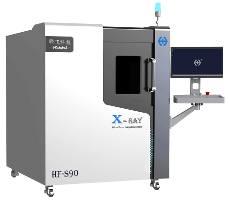
HF-S90: a 90 kV micro-focus X-ray source.
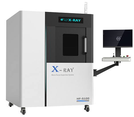
HF-S100: a 130 kV micro-focus X-ray source.
One technical point deserves a candid note: tube voltage determines the penetrating power of the X-rays. Compared with 90 kV, 130 kV offers a better penetration margin for thicker and denser workpieces, and leaves room for improved image contrast under otherwise identical conditions. For this particular sample, the HF-S100 image was indeed the sharper of the two; but the HF-S90 image already rendered the terminal positions and solder condition completely, meeting every acceptance criterion the customer had set.
The customer's final decision was pragmatic and clear: the HF-S90 meets the current requirement, so the HF-S90 was selected; if the product architecture changes, the workpiece thickens, or inspection requirements rise later, the HF-S100 would be considered as an upgrade. We agree with that reasoning; equipment penetration should match the actual workpiece, with a sensible upgrade path reserved, rather than paying for capacity that will never be used.
Figure 1 The Wahfei Technology HF-S90 micro-focus X-ray inspection system |
Figure 2 The Wahfei Technology HF-S100 micro-focus X-ray inspection system (130 kV) |
4. On-Site Validation: HF-S90 Imaging Results
Once the customer's samples were loaded, the inspection area was located quickly using high-definition auto navigation and imaged in real time. The following are actual HF-S90 images of the connector samples:
Figure 3 HF-S90 image: the exterior material is aluminum. Morphological details at the welded joints between cables and terminals can be examined to determine whether the welds are full and continuous. |
Figure 4 HF-S90 image: the layout, position and centering condition of internal metal terminals are clearly visible. |
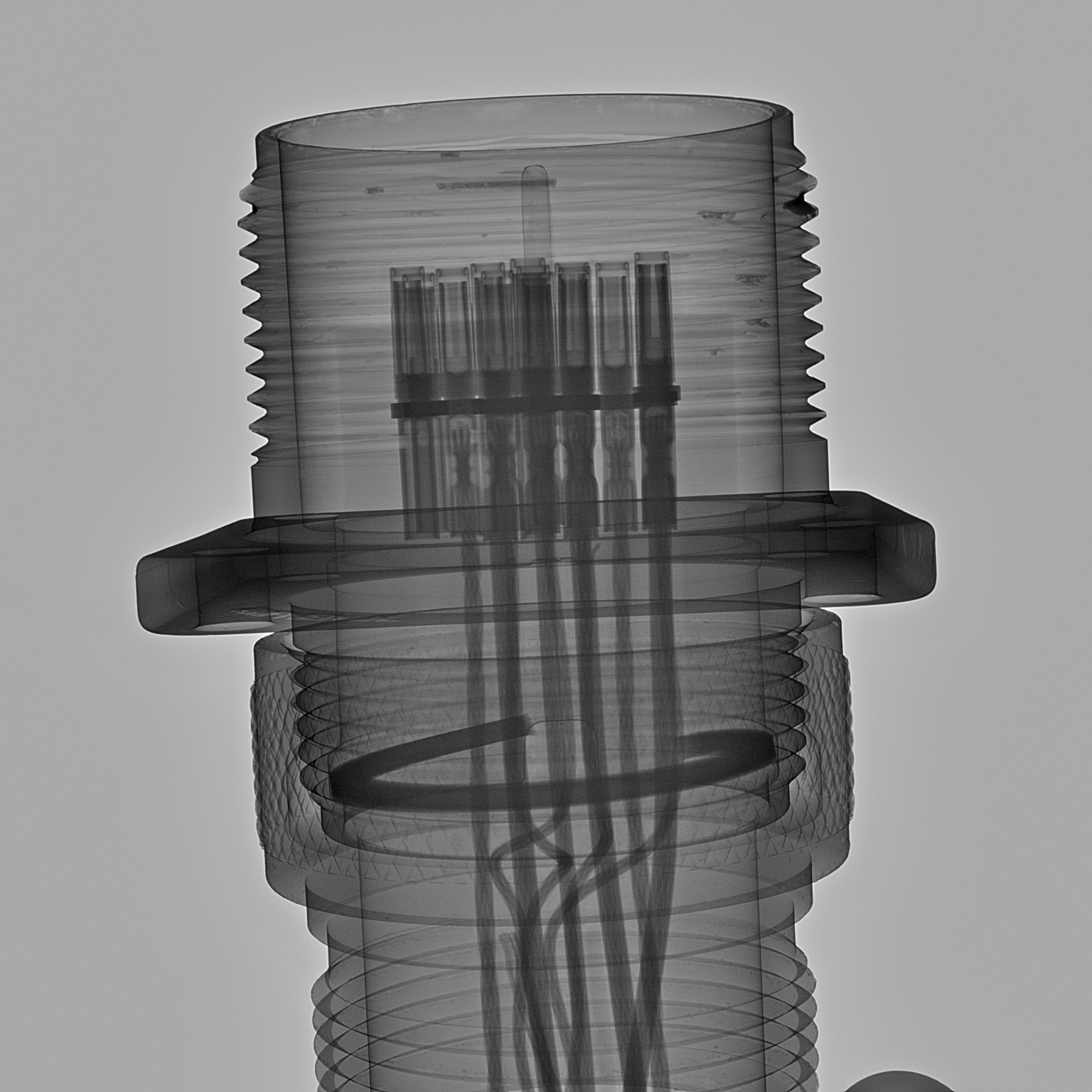
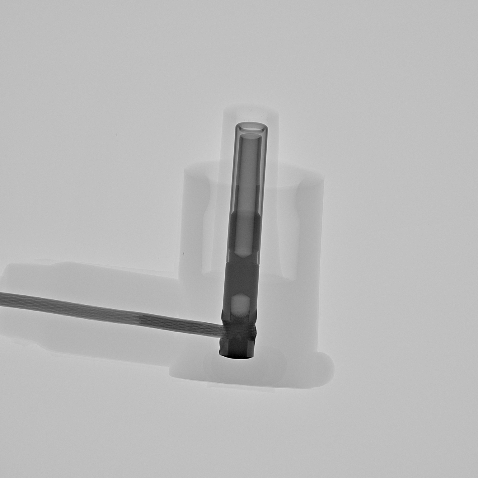
Figure 5 HF-S90 image:the exterior material is steel. |
Figure 6 HF-S90 image:the exterior material is steel. |
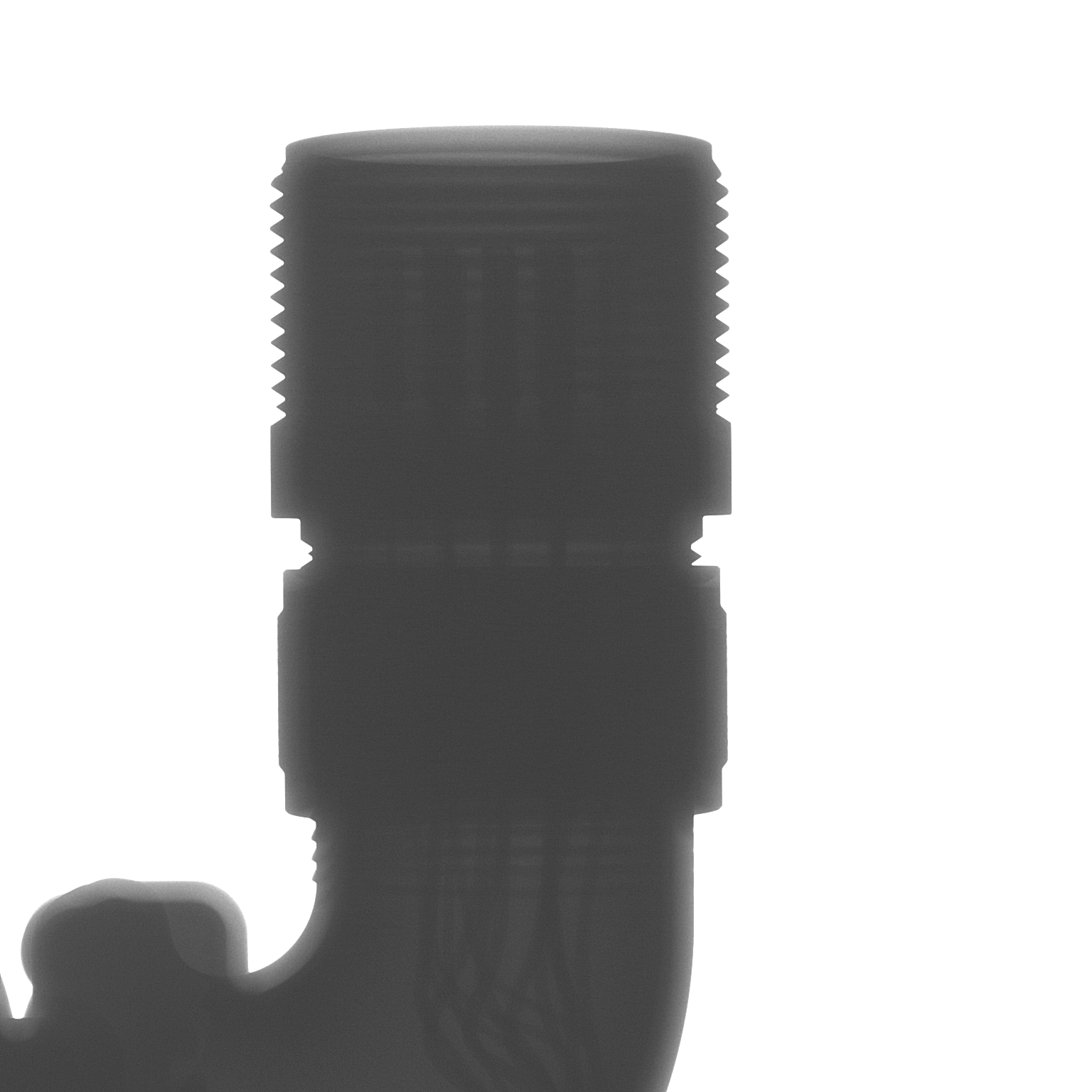
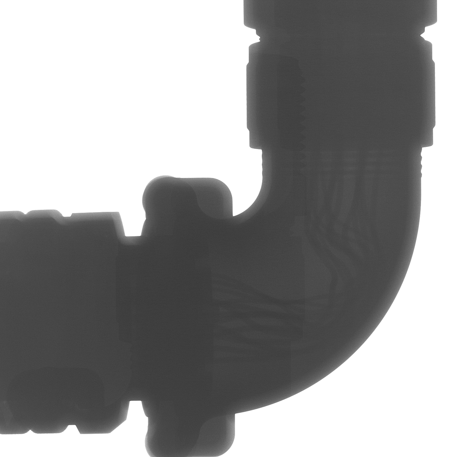
As observed in the image: the relative positions of all internal metal terminals of the aluminum sample are clearly distinguishable. Centering status and offset can be directly compared and evaluated. The contours of welded joints between terminals and cables are continuous and full, with no obvious defects detected in the welding area. Combined with the software’s distance and parallel distance measurement functions, terminal offset can be further quantified to generate recordable and re-evaluable inspection data.
Worth highlighting is the HF-S90's multi-angle inspection capability: the X-ray tube and the FPD rotate concentrically while the stage remains level, with a maximum tilt of 60 degree, without distortion, loss of energy or reduction of the inspection field. For slender metal components such as terminals, adjacent ones may overlap in a single straight-on view; an angled view separates the overlapping structures, which is a very practical way to confirm the spatial relationship between terminals.
5. Same Sample, Side by Side: HF-S100 (130 kV) Imaging Results
So that the customer could compare fully, the same samples were then inspected on the HF-S100. With the stronger penetrating power of its 130 kV source, overall image contrast and detail rendering improved further, and the routing and layout of the conductors inside the molded body became fully resolved:
Figure 7 HF-S100 (130 kV) image of the same sample: greater penetration margin delivers richer detail layers. |
Figure 8 HF-S100 image:The routing of internal wiring harness inside the sample is clearly identifiable. |
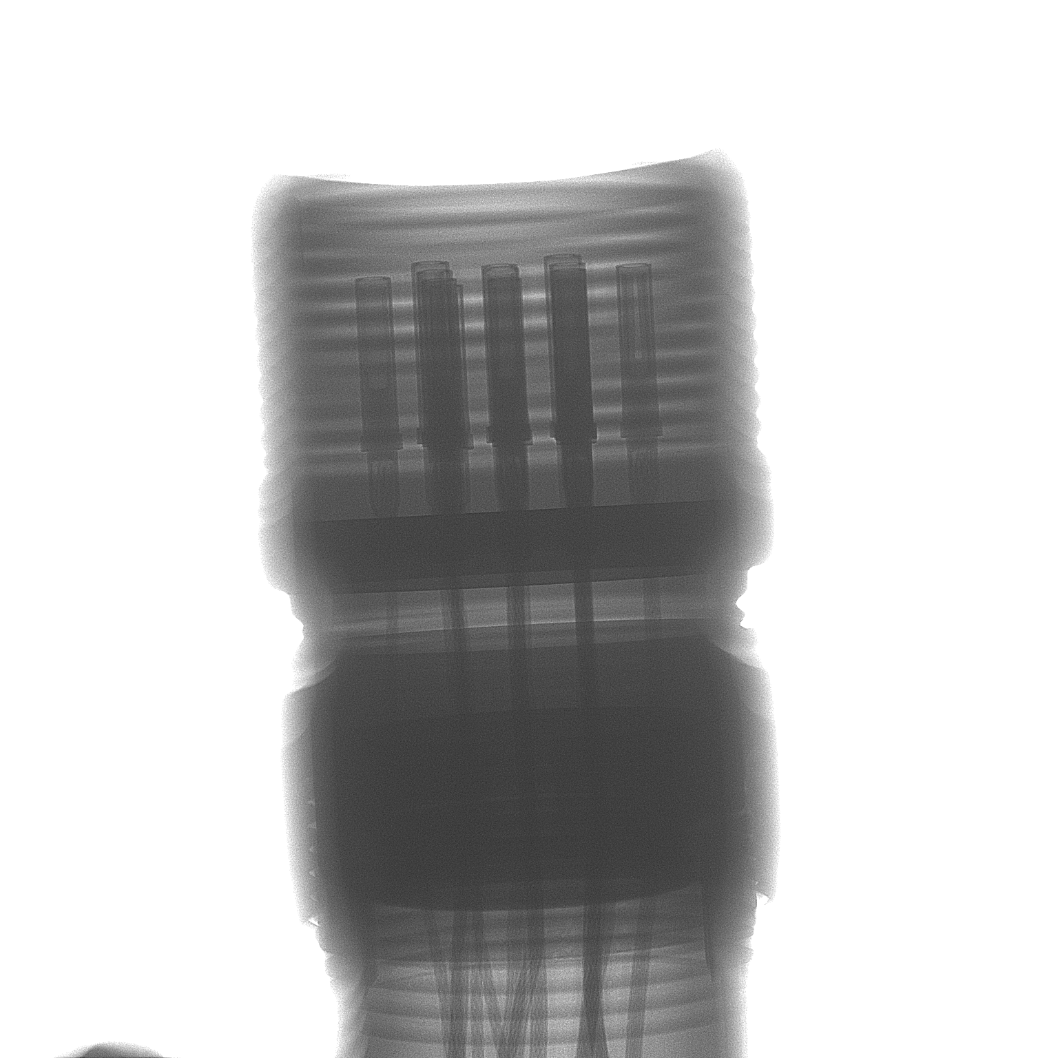
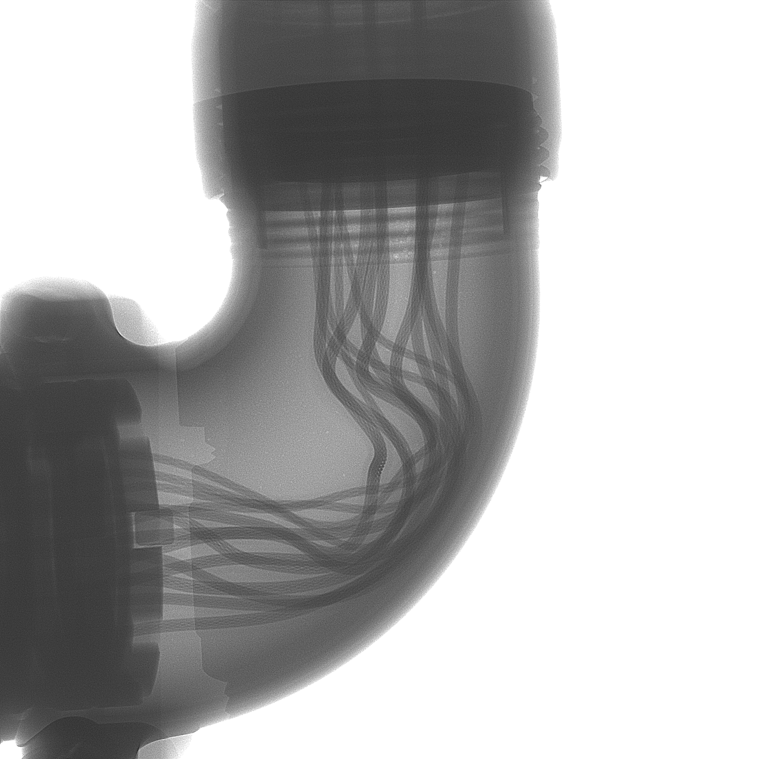
Objectively, the HF-S100 image quality is the better of the two, and that is precisely where the value of a 130 kV model lies: with thicker workpieces, denser materials and more complex structures, a higher tube voltage means a more generous penetration margin and more latitude for parameter adjustment. But for the acceptance objectives of this sample; confirming solder integrity and judging terminal position; the information the HF-S90 delivered was already complete and sufficient. After weighing the results on site, the customer concluded that the HF-S90 should be selected for the current requirement, with the HF-S100 held as an option for a future upgrade.
6. On Site with the Customer: Visible Verification Process
Inspection performance is not something you argue about; it is something the customer sees for themselves. On the day of the visit, the customer watched the sample images live in the showroom and went through terminal position judgment, the software's measurement functions and inspection efficiency point by point with our engineers. Our sales manager then gave a full briefing in the workshop on machine construction, operating procedure, safety interlocks and after-sales support.
Figure 9 The customer reviewing the sample images on site |
Figure 10 Our sales manager briefing the customer on the equipment |
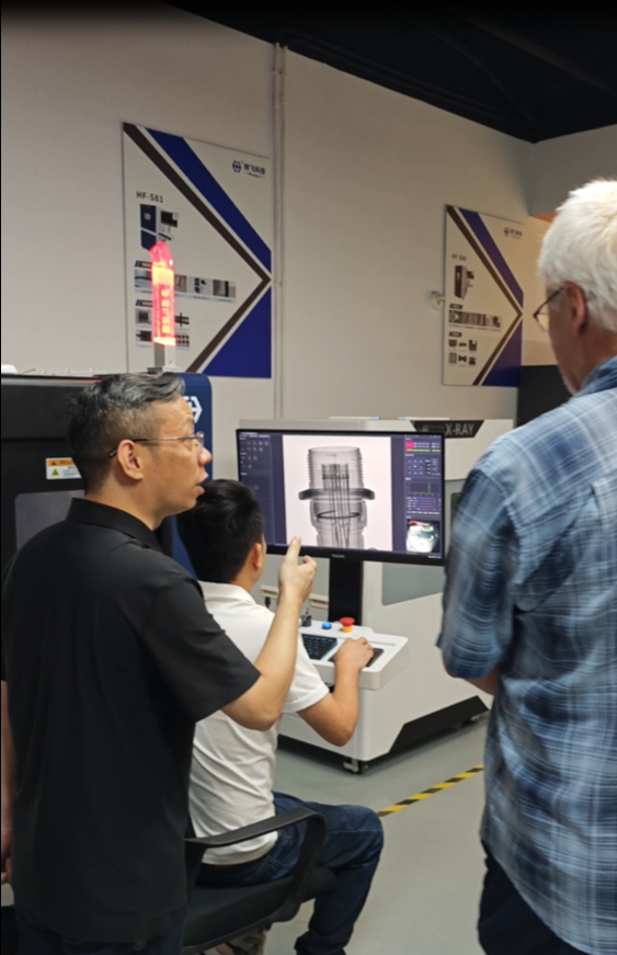
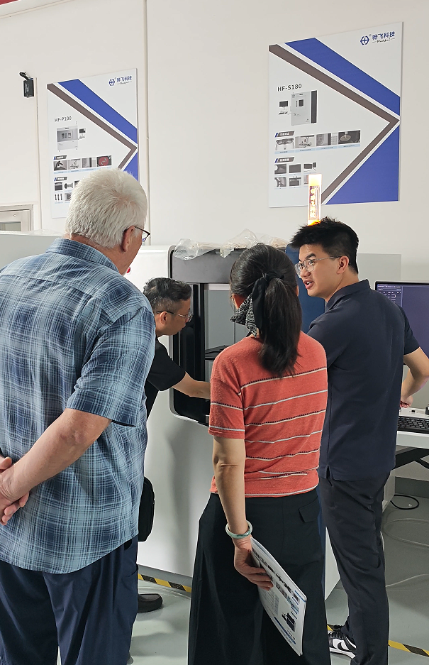
Bringing samples for real testing and validating on site is the way we have always worked: whether the equipment can solve the customer's problem is a question for the sample images to answer first. A selection recommendation is built on real imaging results, not on a paper comparison of specification tables.
7. Value for Quality Control of Connector Manufacturers
Convert the internal condition of samples into determinable and quantifiable data.: terminal displacement can be quantified and recorded through distance and parallel-distance measurement, so acceptance no longer rests on rough visual judgment, and results can be compared and traced from batch to batch;
Solder quality is intercepted before shipment: hidden risks such as cold joints and insufficient solder are identified before delivery, instead of surfacing as poor contact or an open circuit after terminal assembly;
Non-destructive sampling: X-ray inspection neither touches nor damages the sample, so parts can continue through production afterwards; inspection programs are saved per part number and can be recalled at any time, which suits batch sampling and outgoing quality checks;
Selection with an upgrade path: choose the tube voltage that matches the current workpiece (90 kV), and move up to a 130 kV model if workpieces thicken or requirements rise, with the same software and operating framework and low migration cost.
8. Frequently Asked Questions (FAQ)
Q1: How should I choose between 90 kV and 130 kV?
Tube voltage determines penetrating power, so the choice should match the thickness and material density of the workpiece. For these connector samples, 90 kV met every acceptance requirement; for thicker or denser workpieces, or where greater latitude in parameter adjustment is wanted, the 130 kV HF-S100 is the better fit. The most reliable approach is to bring samples for a side-by-side test; let the images decide.
Q2: Will inspection damage the connector samples?
No. X-ray inspection is non-destructive: it does not touch the sample and does not alter its mechanical or electrical properties, so the part can continue through production after inspection.
Q3: How is radiation safety ensured?
Both systems keep X-ray leakage below 1 uSv/h and are fitted with door safety interlocks: the X-ray source cannot start unless the door is properly closed; the front door locks automatically during operation; and if the door is forced open, the X-ray source is cut off before the door opens.
About Wahfei Technology: Wahfei Technology specializes in the development and manufacture of industrial X-ray inspection equipment, with a product range covering 90 kV and higher-voltage micro-focus models for non-destructive inspection in electronics manufacturing, connectors, semiconductor packaging, wire and cable, and other fields. We support customers in bringing samples for on-site testing and validation, using real inspection images to guide the selection decision. To arrange a sample inspection or to request the full technical datasheets, please contact us.
Note: the inspection images and conclusions in this article are based on on-site testing of customer-supplied samples and serve to illustrate the inspection capability and methodology of the equipment. Acceptance criteria for specific products should follow the quality specification agreed between supplier and customer. Customer details have been anonymized.