



Intermittent Opens and Poor Contacts in Sensors: Can the Root Cause Be Found Before the Product Ships?
- Pubdate 2026-10-10
When a sensor develops an internal open circuit or a poor contact, it rarely fails outright. The symptoms are usually intermittent loss of signal, fluctuating readings, or output drift, while the root cause sits inside the housing and the potting compound. Using sensor samples submitted by a customer, this article explains how industrial X-ray non-destructive inspection can verify the continuity of the top lead wire and the condition of the solder joint at the bottom.
1. Why These Defects Are So Hard to Catch
The conductive path inside a sensor typically runs: top lead terminal → fine wire → bottom solder joint and cable. Damage at any point along that path shows up directly as abnormal electrical performance. The problem is that both critical locations sit inside the housing:
Top lead wire: very small in diameter and covered by the housing or the potting material. It can be thinned or even broken during assembly, potting, bending, or vibration, and the break stays inside the housing, leaving no mark on the outside;
Bottom solder joint: covered by the cable jacket, heat-shrink tubing, or potting compound, so a cold joint, insufficient solder, or a cracked joint will not appear in a visual inspection.
The limits of conventional methods are equally clear. Electrical testing can only answer whether the part conducts at this moment; it cannot say whether the internal structure has already been weakened, or whether it will survive the vibration and temperature cycling that follow. Visual inspection cannot see inside the housing. Vibration and thermal-cycling tests can expose the problem, but only after the fact. For many manufacturers the reality is this: the goods have already shipped, intermittent failures appear at the customer's end one after another, and only after rework and teardown does the broken wire or the separated joint become visible — by which point it is very difficult to trace which batch or which process step introduced it.
2. X-Ray Transmission: Turning an Encapsulated Structure into a Grayscale Image
As X-rays pass through a sample, different materials attenuate them to different degrees. The detector captures the transmitted intensity and converts it into a grayscale image: high-density materials such as metal conductors and solder attenuate strongly and appear dark, while low-density materials such as potting compound, insulation, and air attenuate weakly and appear bright.
On this basis, the routing of the wire, the shape of the solder joint, and the strand structure of the cable — all hidden inside the housing — are presented directly as differences in brightness. This is a direct result of how the materials absorb radiation; it neither requires nor should depend on disassembly.
Image resolution is a key prerequisite for inspecting fine wires. Wahfei Technology's micro-focus X-ray inspection systems use a micro-focus X-ray source with a focal spot size of 5 µm, paired with a high-resolution flat-panel detector, so that wire edges remain sharp after geometric magnification. This is precisely what the judgment of "has the wire been thinned" and "is there a gap at the break" depends on. If the focal spot is too large, the edges of a fine wire suffer penumbral blurring — blurring the very defects that most need to be seen.
One imaging characteristic is worth noting: the grayscale value at the edge of the housing is often deeper than at its center, because rays travel a longer path through the material at the edge. This is normal imaging behavior and should not be misread as an internal defect.
3. Two Things We Look At in These Samples
|
|
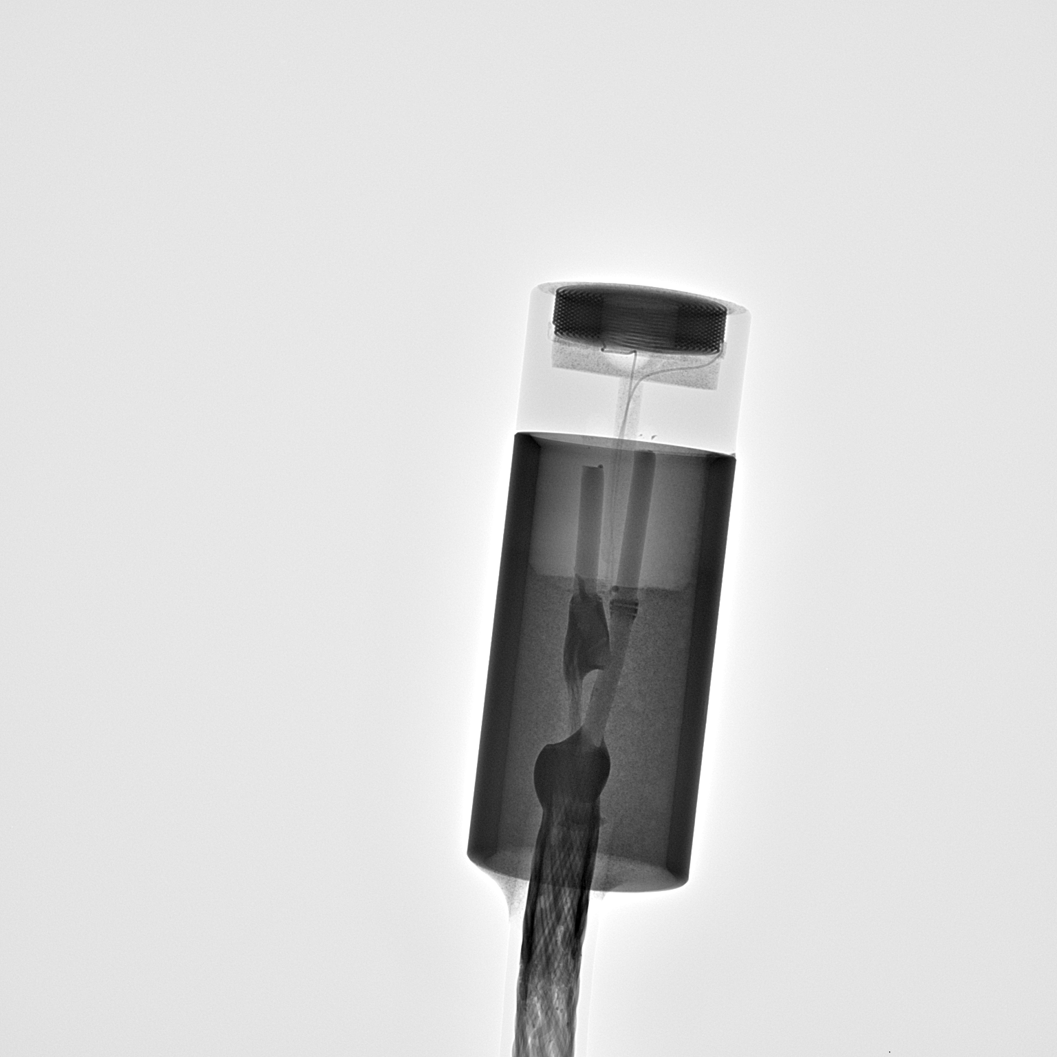
In the overall X-ray image of one sample, the fine wire leading out of the upper component can be traced clearly as it enters the housing and bends inside it, while the braided cable exiting through the bottom of the housing shows its braid texture distinctly.
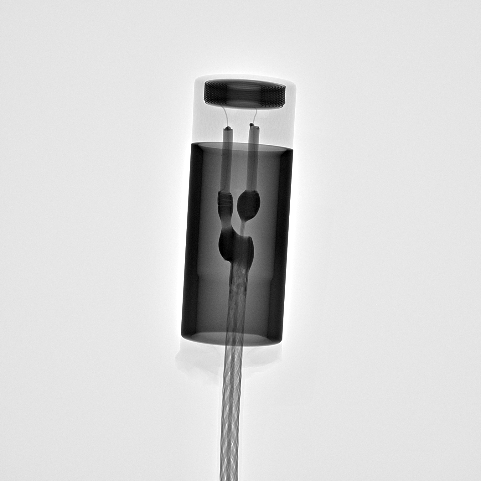
In the image of the other sample, two fine wires and the solder joints at their respective lower ends appear separately, each joint forming a distinct thickened dark region, so that the connection between the wires and the cable is immediately readable.
Both samples were imaged on the same model of equipment, and their internal structures are rendered with clear grayscale contrast, so wire routing, joint position, and joint shape can all be read directly. It should be noted that in samples of this type, a single projection angle compresses components at different depths onto one image; where wires or joints overlap, a defect located behind or close to the housing wall may be obscured. Adding suitable imaging angles for a given sample is the prerequisite for a complete view of the internal structure.
First: continuity of the top lead wire
What is being assessed is not how dark the wire looks, but whether its form is continuous and uniform. A sound wire appears as a continuous dark line of even grayscale and essentially constant width, with straight edges. A break appears as an interruption of the dark line, an abrupt change in grayscale, and misalignment of the two broken ends. Necking or thinning appears as a clear local narrowing of the wire and a lighter grayscale — a "stretched but not yet broken" condition that in reliability terms deserves more caution than an obvious break, because it may pass the current electrical test and still fail later under vibration or temperature rise. Partial strand breakage in a stranded wire appears as fewer strands at that point, a thinner cross-section overall, or a gap in the braid pattern.
Second: connection condition of the bottom solder joint
A solder joint appears in the image as a thickened, relatively regular dark region whose function is to connect the wire to the cable. What to look for: whether the solder continuously covers and wraps the junction of wire and cable; whether a gap or discontinuity exists at the junction (the typical signature of a de-soldered or cracked joint); whether the amount of solder is clearly too small or abnormally built up; whether bubbles or voids are present inside the joint (visible as brighter patches within the solder); and whether the joints on multiple wires are consistent in size and shape — the consistency of joints within a batch is itself an indicator of soldering process stability.
One boundary should be stated objectively: X-ray imaging reveals the geometry and distribution of a solder joint, but it does not reflect metallurgical wetting quality or the state of intermetallic compounds. Observing no geometric abnormality does not prove that the soldering process is sound; observing a gap, a crack, or missing solder, however, does establish that the connection is unreliable. Its role is rapid structural screening and process monitoring, and it does not replace cross-sectioning or electrical testing.
4. What This Means for Manufacturers
Turning an invisible risk into a judgeable image: wire continuity and joint condition move from "confirmable only by teardown" to "confirmable before the product leaves the line";
Sampling without destroying the sample: X-ray inspection touches nothing and damages nothing, so inspected products continue through normal flow, and the same sample can be re-inspected and archived for comparison;
Intercepting risk before shipment: it reduces the probability of intermittent failures erupting across a batch after delivery, along with the rework, returns, and reputational costs that follow;
Evidence for process improvement: if wire necking clusters at one bending station, or undersized joints cluster on one machine, the image data links the failure mode to the process step;
Complementary to electrical testing: electrical testing confirms "conducts now", X-ray confirms "structurally intact" — only together do they support a more confident judgment of reliability.
5. Where It Applies
Beyond sensors, the same need to verify the connectivity of internal fine wires and solder joints exists in connectors and terminal blocks, harness and cable assemblies, relays and switches, winding leads of small motors, piezoelectric elements and transducers, and all kinds of potted or molded electronic modules. What these products share is this: the connection point is the functional lifeline, and every one of them is hidden by a housing or an encapsulant.
6. Frequently Asked Questions (FAQ)
Q1: Can X-ray inspection replace electrical testing?
No. The two answer different questions. Electrical testing answers "does it conduct right now"; X-ray answers "is the internal structure intact". A wire that has been thinned but not yet broken can pass electrical testing and still fail later under vibration or temperature rise, and that kind of risk is visible only in a structural image. The two are complementary, not interchangeable.
Q2: The wire is so fine — can X-ray really resolve it?
It depends on focal spot size and magnification. The smaller the focal spot, the narrower the penumbra at the edges after geometric magnification, and the less the wire contour and defects are blurred away. This is why applications of this kind generally call for a micro-focus system with a 5 µm-class focal spot.
Q3: Why is multi-angle imaging necessary?
At a single projection angle, wires and joints at different depths in samples of this type overlap one another, and a defect located behind or close to the housing wall may be hidden. Imaging at an angle separates the overlapping structures and lowers the risk of a missed call.
About Wahfei Technology: Wahfei Technology focuses on the development and manufacture of industrial X-ray inspection equipment. Our product range covers micro-focus inspection systems from 90 kV to higher voltage classes, widely used for non-destructive inspection in electronics manufacturing, sensors, connectors, semiconductor packaging, and wire and cable. We support customers in validating equipment with their own samples, using real inspection images to aid judgment and model selection. To arrange a sample inspection or obtain full technical specifications, please contact us.
Note: The inspection images and conclusions in this article are based on actual measurements of customer-submitted samples and are intended only to illustrate the equipment's inspection capability and method. Inspection criteria for specific products should follow the quality specification agreed between supplier and customer. Customer information has been anonymized.