



Inductor Internal Nondestructive Inspection: Industrial-Grade Application of the HF-S100 X-Ray Inspection System for Winding Defect Detection
- Pubdate 2026-08-19
A business partner recently sent a batch of inductor samples to our laboratory for internal nondestructive imaging using the HF-S100 industrial X-Ray inspection system. Taking this real inspection as a starting point, this article systematically introduces the HF-S100's imaging capability and process adaptability for the typical defects encountered in inductor manufacturing — false joints, cold solder, open circuits, and uneven winding — and discusses the engineering value of its key modules: micro-focus X-Ray source, flat-panel detector, 60° tilt mechanism, and 360° rotating stage.
1. Why Inductor Inspection Has Become a Critical Quality Node in Electronics Manufacturing
As a core passive component in power modules, RF front-ends, DC-DC converters, filter networks, and automotive-grade controllers, the inductor directly determines the electromagnetic compatibility, conversion efficiency, and long-term reliability of the entire system. In high-reliability applications such as new-energy vehicles, photovoltaic energy storage, 5G communications, and AI computing servers, inductor failures often trigger systemic faults. Such failures tend to be batch-related and reproducible, making root-cause tracing extremely costly.
Inductor failure modes are closely tied to the manufacturing process. Common defects include:
False Weld: the solder appears wetted on the surface, but no effective intermetallic compound (IMC) layer is formed at the interface; both mechanical and electrical performance fall short of specification;
Cold Solder (Dry Joint): poor solder wetting or insufficient heating leads to low joint strength and elevated contact resistance, which often evolves into an open circuit after thermal cycling;
Open Circuit: the enameled wire is mechanically damaged during winding, or the lead breaks under long-term thermal stress at the joint, directly causing inductor failure;
Winding Misalignment: uneven coil arrangement, inter-layer misalignment, or turn-to-turn short circuits cause inductance drift, reduced Q factor, and increased magnetic leakage.
Most of these defects are located inside the inductor package. Traditional visual inspection, AOI, and even ICT electrical testing struggle to identify them effectively at the final inspection stage. Obtaining a clear internal structure image without destroying the sample has therefore become a core requirement for process improvement, batch judgment, and incoming material inspection. X-Ray transmission imaging has become the preferred solution for internal inductor inspection because of its non-destructive nature and high contrast for metal, ceramic, and magnetic materials.
2. Customer Sample Case: HF-S100 Imaging of Inductor Internal Structure
Case Background: The customer submitted multiple inductor samples and requested transmission imaging of the internal winding, solder joints, and lead connections to assess process stability before mass production. The inspection was performed on our HF-S100 platform. The operator placed the samples steadily on the 600 mm × 600 mm extra-large stage and used one-click navigation to locate the viewing field, completing multi-angle, multi-view imaging.
The images below show the X-Ray transmission result of the customer's inductor samples on the HF-S100. The number of winding layers, their routing direction, and the lead-end positions are clearly resolved:
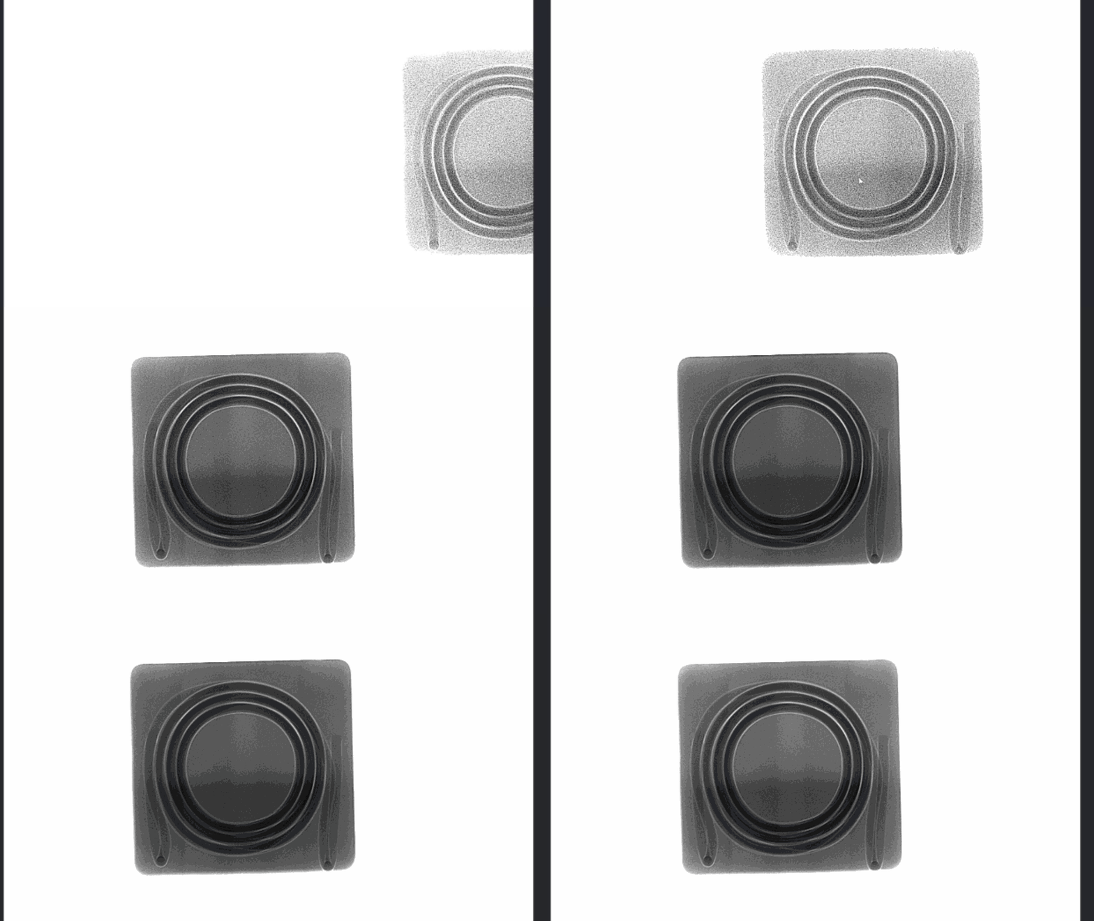
Fig.1 HF-S100 top-view imaging — multilayer concentric winding structure clearly resolved
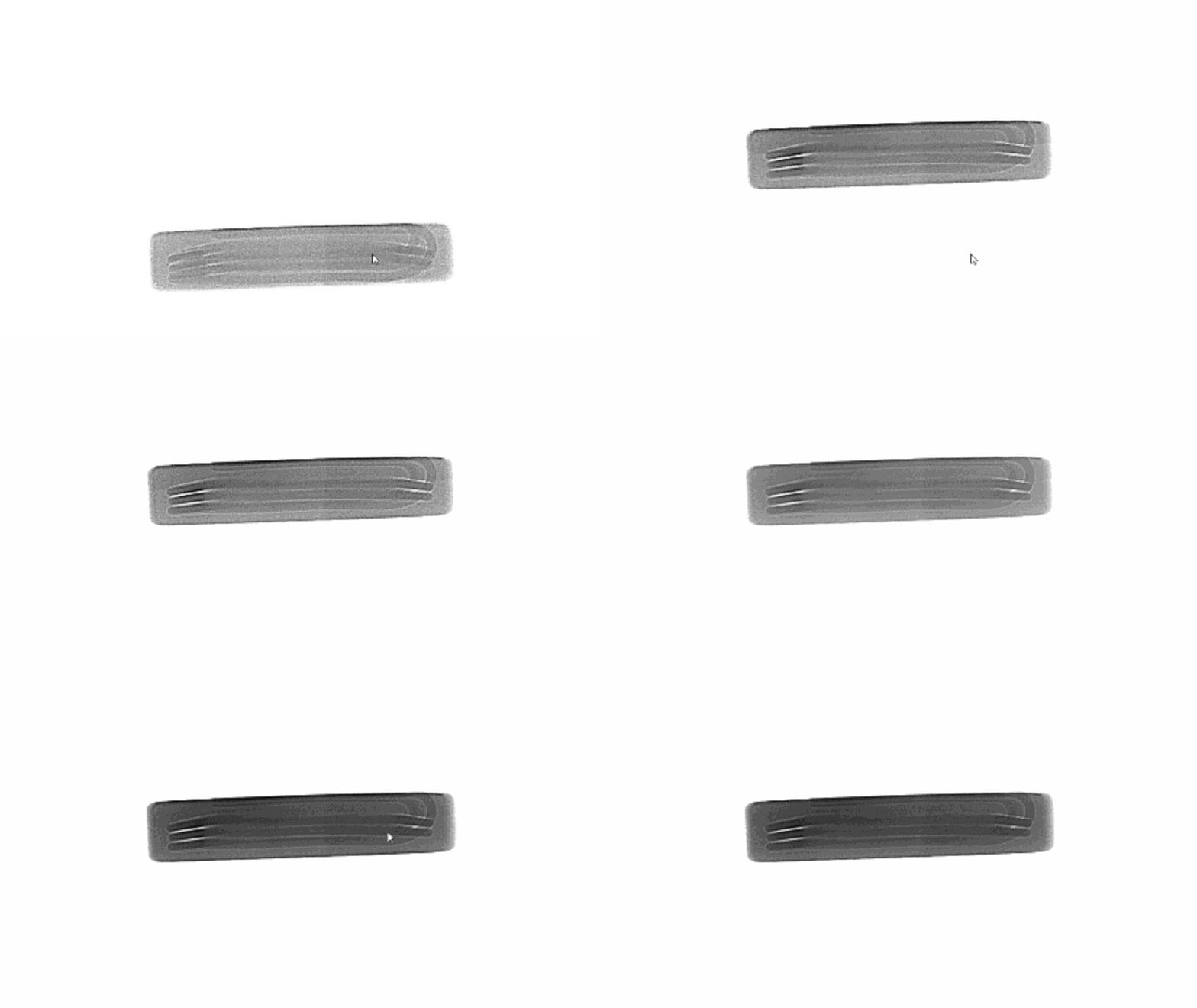
Fig.2 HF-S100 side-view imaging — lead-end solder joint and turn-to-turn arrangement
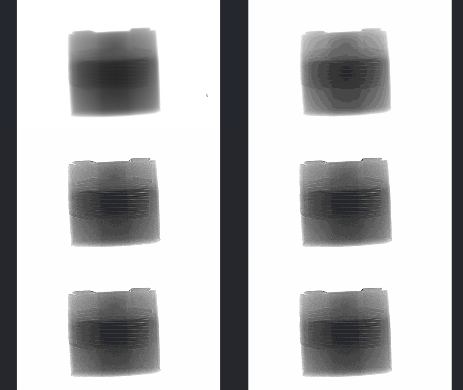
Fig.3 HF-S100 full transmission — internal panorama of the packaged inductor
2.1 Inspection Item 1: False Joints and Cold Solder
The inductor's lead solder joint is a typical high-failure zone. Under X-Ray, the void ratio, wetting angle, and IMC morphology of the joint can all be assessed through grayscale differences. The HF-S100 is equipped with an FPD featuring 16-bit AD conversion, delivering 65,536 grayscale levels. It clearly distinguishes the boundaries between solder and base metal, and between solder and air cavities, providing a quantitative basis for process engineers' judgment.
2.2 Inspection Item 2: Open Circuit
Enameled-wire breakage is often caused by abnormal winding tension, incomplete enamel stripping, or stress concentration at lead bends. In the orthographic X-Ray view, a broken coil shows features such as discontinuity at the end and abnormal shadow length. Combined with the 60° tilt mechanism, the HF-S100 can bypass sample occlusion to obtain the optimal viewing angle of the fracture, avoiding missed detections.
2.3 Inspection Item 3: Winding Misalignment and Turn-to-Turn Short
Inter-layer misalignment, local bulging, or collapse distorts the magnetic field distribution and affects the nominal inductance and saturation current. With a 5.8 LP/mm high-resolution detector (85 μm pixel size) and a 130 kV / 5 μm micro-focus source, the HF-S100 resolves micron-level coil undulation within the 130 mm × 130 mm field of view — suitable for fine inspection of small power inductors such as 0402 and 0603 packages and automotive-grade molded inductors.
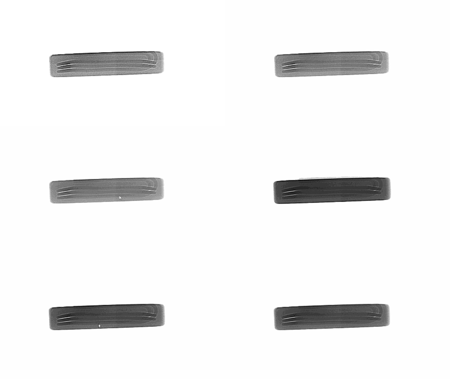
Fig.4 HF-S100 high-resolution side-view imaging — winding layers and lead-end status
3. HF-S100 Engineering Design: Optimized for Industrial-Grade Inspection of Inductor-Type Samples
Compared with general-purpose X-Ray platforms, the HF-S100 is optimized at multiple levels for small, high-density electronic components. The key points are detailed below.
3.1 Micro-Focus Source and High-Resolution FPD
The HF-S100 uses a 130 kV micro-focus sealed tube with a focal spot of only 5 μm and a maximum tube current of 300 μA, balancing high penetration with high resolution — well suited to high-density packages such as ferrite cores and metal alloy powder cores. The detector is a high-resolution digital flat-panel detector (FPD) with 5.8 LP/mm resolution, 85 μm pixel size, 1536 × 1536 pixel matrix, 130 mm × 130 mm acquisition FOV, 20 fps frame rate, and 16-bit AD acquisition, yielding real-time imaging without noticeable ghosting.
3.2 60° Tilt + 360° Rotation: Designed for "Cylindrical / Flat" Inductor Packages
Inductors are physically shaped as flat rectangles, cylinders, or vertical through-hole parts, with internal defects often hidden in viewing-angle blind spots. The HF-S100 adopts a synchronous concentric rotation scheme for the X-Ray source and FPD:
The stage remains horizontal at all times; no special fixture is needed, eliminating the risk of sample dropping;
When the angle changes, the central ray remains aligned on the sample — no distortion, no aberration, no energy loss;
Maximum tilt is 60°, and when combined with the optional 360° horizontal stage rotation (Φ550 mm), it enables stereoscopic perspective of the inductor from any azimuth;
Compared with the two traditional approaches — tilting the stage, or tilting only the detector — this scheme simultaneously improves operational convenience, inspection range, and image fidelity.
For inductor samples, the greatest value of the 60° tilt mechanism is that the three "blind zones" hard to observe from the top view — solder-joint end face, lead root, and inter-winding layer — can now be imaged at the optimal angle through tilt.
3.3 Three-Color Safety Status Light: Making "Is the Beam On?" the Most Intuitive Visual Signal
Radiation safety of X-Ray equipment is the primary concern in high-frequency use scenarios such as electronics factories, SMT lines, and laboratories. The HF-S100 features a three-color status indicator on its exterior:
Front door not closed — Blue: reminds the operator to close the door; the equipment is in a standby protective state;
Front door closed, X-Ray not started — Green: the equipment is ready, awaiting the operator's exposure command;
Front door closed, X-Ray started — Red: clearly indicates active exposure, warning nearby personnel to keep a safe distance.
The blue–green–red sequence covers the entire workflow from "safe — ready — exposing," allowing the operator to judge the equipment status without looking at the screen, significantly reducing the risk of entering the radiation zone. This design is especially suitable for multi-shift, multi-operator production lines.
Radiation Safety Measurement: Measured by a third-party radiation detector, the HF-S100's leakage dose rate at the rated condition is below 1 μSv/h on both the front and side faces. Benchmarked against the ICNIRP public dose constraint of 1 mSv per year, this measured value already covers the most stringent real-world conditions. Combined with the lead shielding and interlock design, it meets the occupational-health requirements for long-term continuous operation on production lines.
3.4 600 mm × 600 mm Extra-Large Stage + CNC Programming
The HF-S100 is configured with a 600 mm × 600 mm stage (Φ550 mm with optional 360° rotation) and a maximum load of 20 kg, allowing multiple inductor samples or an entire tray of parts to be placed at once. Together with the self-developed multi-function image processing system, it supports distance, diameter, void ratio, and solder-climbing height measurements, plus multi-point CNC positioning and NG/OK test-point step annotation — making automated re-inspection of batch samples possible.
4. Beyond Inductors: The Broader Application Map of the HF-S100
Inductor inspection is only one of the HF-S100's application scenarios. Built on the hardware combination of a micro-focus X-Ray source and a high-resolution FPD, the system serves the following segments:
5G Communication: internal structure and solder joints of RF modules, filters, and connectors;
Automotive Electronics: batch quality control of ECUs, automotive-grade inductors, automotive connectors, and wiring harnesses;
Aerospace: incoming re-inspection and failure analysis of high-reliability electronic assemblies;
Electronic Semiconductor Packaging: void ratio, bridging, and misalignment of QFN/DFN/BGA solder balls;
SMT — BGA / QFN Inspection: post-reflow solder quality, head-in-pillow defects, and IMC layer observation;
LED: die bonding, phosphor distribution, and wire-bond loop inspection;
Connectors: terminal crimping, pin alignment, and metal-part position inside plastic;
Wiring Harness: internal conductor structure, shielding layers, and crimp zones;
Lithium Batteries: electrode layer alignment, winding defects, short circuits;
Super Capacitor: carbon-layer winding and tab welding;
Molded Plastic Component: insert position, internal voids, and metal-skeleton distribution.
For electronics manufacturers, the real value of an X-Ray inspection system lies not only in "whether it can see", but in "whether it can see stably, in batch, and quantifiably." Through its hardware-level multi-angle mechanism, light-level safety indication, CNC-level automatic positioning, and software-level multi-type measurement, the HF-S100 aims to transform industrial X-Ray from "an imaging device in the lab" into "a process tool on the production line."
5. Conclusion
As the "silent cornerstone" of electronic systems, the inductor's internal defects must be identified early to secure the long-term reliability of the final product. Built around a 130 kV micro-focus sealed tube, a 5.8 LP/mm FPD, a 60° synchronous tilt mechanism, and an optional 360° rotating stage — complemented by a three-color safety indication and a measured radiation dose of below 1 μSv/h — the Huafei HF-S100 delivers an engineered industrial X-Ray inspection solution across imaging quality, inspection efficiency, and operational safety for inductor components and the broader electronics manufacturing landscape.
If you have samples of inductors, connectors, SMT components, lithium batteries, or molded parts requiring internal structure inspection, you may send them to us for a free sampling evaluation. Our engineers will deliver an HF-S100-based inspection report with multi-angle images, defect annotations, and preliminary process recommendations — supporting your key quality milestones of incoming evaluation, batch sampling, and failure analysis.