


Industrial CT Selection Guide: How to Understand Key Specifications and Choose the Right NDT Equipment?
- Pubdate 2026-04-25
How to Choose an Industrial CT That Truly Solves Production Line Issues
The baseline for product quality in high-end manufacturing is continuously being raised. Whether it’s tiny pores hidden in die-cast parts or cold solder joints inside precision electronic components, traditional destructive sampling inspections are not only costly but also prone to missing defects; conventional X-ray imaging (DR) often only shows overlapping 2D images, making precise localization difficult.
For this reason, modern industrial CT (Computed Tomography), a non-destructive testing device that reconstructs 3D images from projection data, has gradually become standard equipment for leading companies in various industries. Although industrial CT shares basic principles with medical CT in hospitals, its design and structure are significantly different to accommodate diverse industrial inspection objects. So, when faced with industrial CT equipment costing tens or even hundreds of thousands, how can decision-makers overcome the technical barrier and select a "good device" that truly solves production line problems?
1. What Core Pain Points Can Industrial CT Solve for Your Factory?
The essence of industrial CT inspection results is a set of digital image data that visually represents the internal structural characteristics of a workpiece. The original intention of manufacturing industrial CT equipment is to accurately "see through" the internal state of materials without damaging them.
Compared with other traditional non-destructive testing methods, the biggest advantage of industrial CT is that its images are free from interference caused by overlapping structures inside materials. This means it can do far more than just "take a look"; it can address the following in-depth issues:
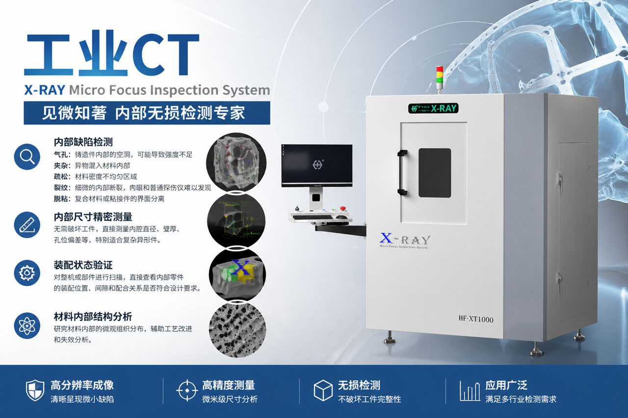
Defect Detection Without Blind Spots: Accurately identify and locate fatal defects such as pores, inclusions, looseness, cracks, and delamination inside materials.
Non-Destructive Internal Measurement: Not only can it analyze internal structures, but it can also precisely measure tiny dimensions inside complex parts, saving the cost of destructive sectioning.
Assembly Integrity Verification: Inspect the assembly position and engagement of internal components without disassembling the machine or sealed parts.
2. Understand the Three Core Performance Indicators in Plain Language
The fundamental criterion for evaluating an industrial CT is how well its generated image data matches the true internal structure of the inspected workpiece. To quantify this capability, the industry recognizes three core physical parameters: density resolution, spatial resolution, and artifacts.
1. Density Resolution: Sensitivity for Detecting Tiny Defects (Most Critical)
Many customers focus on "how small a feature can be seen (spatial resolution)" when choosing a model, but often overlook the more fundamental density resolution.
What is Density Resolution? Broadly speaking, all radiographic inspections detect anomalies as "density changes" against a background image. Density resolution is the device’s ability to distinguish the smallest contrast between details and base material over a given area.
Why is it the most important? If finding defects is like "looking for a white rabbit in the snow," density resolution is the ability to distinguish nearly identical whites. Since industrial CT has no overlapping structure interference, it can detect finer density variations than conventional X-ray. In short, density resolution reflects the "generalized signal-to-noise ratio" of a CT device and is the fundamental indicator of equipment quality.
2. Spatial Resolution: Clarity for Distinguishing Adjacent Details
What is Spatial Resolution? It refers to the system’s ability to identify and distinguish the minimum distance between two tiny details. Images with higher spatial resolution have sharper and clearer boundaries.
Tips to Avoid Pitfalls: For customers focusing on measuring internal dimensions, this parameter is crucial. Note that most current CT technologies are based on 2D slices, and spatial resolution within the slice plane is usually better than in the vertical direction. Therefore, when comparing devices, always ask: which direction’s spatial resolution is specified by the manufacturer?
3. Artifacts: Visual Interference in Images
What are Artifacts? During CT scanning and reconstruction, deviations in physical or mathematical assumptions can create "false appearances" in images that do not exist in reality. These are called artifacts and can be regarded as "generalized noise."
Common Manifestations: For example, low-energy parts absorbed when X-rays penetrate a workpiece can cause "cupping artifacts"; statistical noise of X-ray intensity can introduce "snow-like interference" in images. Excessive artifacts can completely obscure real structural details, rendering the image unusable.
3. How Hardware Configuration Affects Inspection Results
Understanding the technical specifications, we now examine the machine’s hardware foundation. CT image quality depends on the raw projection data, which contains two core pieces of information: X-ray intensity information and scanning position information. Both are nearly equally important.
| Core Hardware Components | Key Selection Considerations | Actual Impact on Image Quality |
|---|---|---|
| X-ray Source | Smaller focal spot is not always better. In theory, a smaller focal spot gives a clearer image, but micro-focus X-ray machines have limited beam intensity due to heat dissipation, 2–3 orders of magnitude lower than standard small focal spot devices, unable to penetrate larger, heavier samples. | A balance between "penetration power" and "statistical noise" is required. Too low X-ray energy causes rapid intensity attenuation, resulting in significant statistical noise (snow-like artifacts across the image). |
| Detector and Electronics | Electronic circuit noise is critical. Detector output signals are weak; electronic circuit noise directly determines the dynamic range of the data acquisition system. | High-quality devices carefully design front-end amplifiers and may even cool the detector and front-end circuits to reduce noise and ensure image purity. |
| Mechanical Scanning System | Industrial CT is like a "CNC machine without cutting tools." Mechanical position data corresponds to X-ray signal coordinates. Mechanical errors should be controlled within 1/3 to 1/10 of a pixel. | If the mechanical system is unstable (especially the rotation center of the stage), images will be severely blurred. Experiments show that a 1-pixel rotation center deviation broadens details to 2 pixels, causing a sharp drop in clarity. |
How to Take the First Practical Step?
Choosing an industrial CT is never just about "comparing spec sheets"; it involves deep integration of physics, mathematics, mechanics, and computer science. A quality industrial CT manufacturer not only provides high-precision hardware but also customized algorithms and scanning strategies tailored to specific materials and defect types.
If you are worried about missing pores in die-cast parts or struggling to measure internal dimensions of precision injection-molded components non-destructively… do not blindly trust paper specifications. We sincerely invite you to bring your samples and contact our technical team for on-site trial testing. Let us use real high-definition 3D data to demonstrate the true strength of a high-quality industrial CT!