Seeing Inside a Wire Harness, Cable or Connector——The joints, crimps and strands that a visual check can never reach
A harness can pass every visual check and every electrical test and still fail in the field. The reason is almost always inside the part: a crimp that never closed around the strands, a pin sitting slightly off position, a conductor that broke where it enters the terminal, a void in a solder joint that only opens up under thermal cycling.
This page is about what industrial X-ray inspection can actually show you in these parts, how to read the images, and where the method stops being useful. We would rather you know the limits before you buy anything.
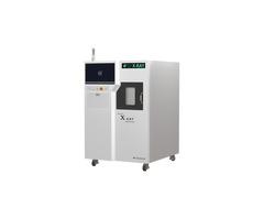
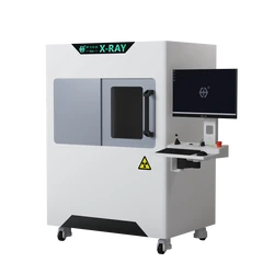
X-rays pass through plastic and aluminum. Denser metal absorbs more of them. What reaches the detector becomes a projection image of the metal inside the part: strands, crimp barrels, pins, solder, and the empty space between them. Nothing is cut, opened or coated. The part goes in as it came off the line and comes out unchanged. Systems built for this work are used in automotive harnesses, consumer-electronic connectors, communication cable, precision terminals, medical electronics, aerospace and industrial automation. |  |
01
Why these defects stay hidden
Every part that matters in a harness is enclosed. The crimp closes inside the terminal barrel. The solder joint sits under the connector body. The strands of a conductor disappear into the barrel, and what happens to them in that last few millimeters decides whether the connection survives vibration and heat.
Visual inspection stops at the surface. Cross-sectioning does show the inside, but it destroys the sample, takes preparation time, and only tells you about the one part you cut. That is why these problems tend to surface late, as intermittent contact, local heating, or a signal that drops out only when the assembly is under load.
The parts themselves have also become harder to check. Higher voltage, higher current and denser packaging mean less margin for a crimp that is only partly closed, or a pin that is a few tenths of a millimeter out of place.
02
Six things worth checking
These are the areas where the method earns its place on a production floor. Each one is a question you can answer from an image rather than an opinion.
CONDUCTORS Conductors and strands Broken conductors, missing strands, deformed or flattened wire, an off-center core, and irregular spacing in multi-core cable. Strand count and cross-section can be measured and compared with the drawing, which catches the fault a pull test can pass by luck. | CRIMP Crimp and terminal Crimp height and width, gaps left inside the barrel, over- and under-crimping, terminal deformation, and how deep the wire actually sits. Foreign material trapped in the barrel shows up too, and a closed-barrel terminal can be checked for gaps where it should have folded shut. |
SOLDER Solder and joints Cold joints, too little or too much solder, voids inside the joint, solder bridging two pads, and whether the two surfaces are actually touching. Wicking into stranded wire can be seen too, which matters wherever flex follows the joint. | CONNECTOR Connector and plug Missing pins, bent pins, pins shifted out of position, assembly errors, a plug fitted the wrong way, latch problems. On overmolded connectors the insert position and internal clearance can be checked in the finished part. |
INSULATION Insulation and overmolding Wall thickness variation, breaks in the insulation, voids, cracks, foreign material and separation between layers. In molded areas: resin fill, shrinkage voids, and whether the insert sits where the drawing says it should. | AUTOMATION Automatic judgment AI-assisted defect recognition with an automatic OK/NG call, run against a saved inspection recipe. Results are logged, so a batch can be reviewed later and a trend caught before it becomes a return. |
03
Three images, and what to look at
Reading these images takes a minute of practice. The rule is simple: dark means dense, light means empty. Metal shows as dark grey, plastic as a pale haze you can see through, air and voids as near-white.
 |  |
Both images come from real parts, not rendered models. That is the useful part: what you see here is roughly what an operator sees on the screen, at the resolution the machine actually delivers.
What this replaces is not the microscope, but the decision you make every time you want to check a part and cannot afford to cut it open.
04
The defects this covers
Broken conductor | Missing strands | Poor crimp |
Damaged terminal | Voids and gas pores | Misalignment |
Foreign material | Internal cracks | Incomplete insertion |
Deformed connector | Inconsistent structure | Hidden assembly defects |
05
Where X-ray stops
No method sees everything. These two points decide whether X-ray is the right tool for a given part, and we would rather say them up front than have you find out later.
01 Penetration and resolution pull against each other. Getting through a thick busbar and still resolving a tiny void are competing goals. Settings have to be chosen for the part in front of you, and the result is always a trade-off. 02 The machine does not set the acceptance limit. Whether a void is acceptable is a question for your drawing, your customer's specification or the applicable standard. We can measure it; the limit has to come from you. |
06
Two places it fits
SAMPLING Pull a part per shift or per batch and check it against the same recipe. Trends show up before the rate does. | IN LINE On high-volume parts, an automated system can inspect every unit and pass or reject it without an operator in the loop. |
If you have a part you are not sure about, send it to us.
We will image it on our equipment and send back the images with a short note on what they show and what they do not. There is no charge for this, and no obligation afterwards. It is the fastest way to find out whether the method answers your question.
Send a sample |
Shenzhen Wahfei Technology Co.,Ltd. builds industrial X-ray inspection systems for electronics manufacturing, semiconductor packaging, power modules, batteries, wire harnesses and precision parts.
The images on this page come from real inspections. What a specific part will show depends on its geometry, its materials and the inspection settings used.
WhatsApp +86 189 0297 8624 | szwahfei@gmail.com | www.szwahfei.cn