BGA Soldering: Process Controls, Defects, and Inspection Limits
BGA Soldering: Process Controls, Defects, and Inspection Limits
BGA soldering joins a ball grid array package to a printed circuit board through solder balls beneath the package. Because the joints are hidden after placement, assembly quality depends on controlling the process before and during reflow, then using suitable inspection and electrical evidence after assembly. No single inspection image can replace a validated soldering process.
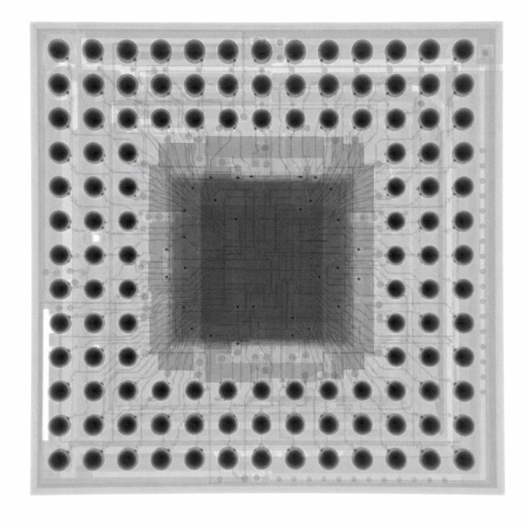
verified BGA soldering or reflow-process image
What makes BGA soldering different?
A ball grid array (BGA) uses an array of terminals on the underside of an integrated-circuit package. During surface-mount assembly, the package is aligned to PCB lands with solder paste or another specified joining arrangement, then heated so the solder forms connections. Unlike perimeter-leaded packages, most BGA joints cannot be directly viewed after assembly.
The final joint is influenced by the package and board design, land pattern, solder paste deposit, component and PCB condition, placement, and reflow profile. These variables interact. A defect such as non-wet open or head-in-pillow cannot be attributed to one cause without evidence from the actual process and materials.
Which process controls matter?
BGA soldering quality starts with controlled inputs. The assembly team should use the released package and PCB data, qualified materials, suitable stencil apertures, and a placement setup matched to the package pitch and board design. Moisture-sensitive components should be handled according to their supplier requirements.
Paste printing: verify deposit consistency and stencil condition for the specific land pattern.
Placement: check alignment, board support, and package orientation before reflow.
Reflow: develop and record a profile appropriate to the solder alloy, package, board mass, and component limits. There is no universal temperature recipe for every BGA.
Change control: reassess the process when a material, package, PCB revision, or equipment condition changes.
IPC-7095E, published by IPC in 2024, is titled “Design and Assembly Process Guidance for Ball Grid Arrays (BGAs).” It is guidance for BGA implementation; acceptance requirements should be determined from the applicable product specification, contract, and workmanship documents rather than inferred from the guide alone.
How should BGA soldering defects be investigated?
Common concerns include bridging, insufficient solder, voiding, misalignment, and incomplete joining. X-ray imaging can reveal selected internal geometric features, while electrical tests evaluate circuit behavior under their defined test conditions. Visual inspection can assess accessible surfaces and process evidence. Each method answers a different question.
For example, an X-ray image may show a bridge between adjacent solder balls or a void projected within a joint. A two-dimensional projection can superimpose structures along the beam path, and some interface conditions may be difficult to distinguish. A suspicious image therefore needs interpretation against the product criteria and, when needed, complementary analysis.
What should be verified after reflow?
Post-reflow verification should combine process records with inspection appropriate to the product risk. A sample plan may include visual checks for accessible features, X-ray inspection for selected hidden joints, and electrical or functional tests for required behavior. The manufacturer should define the inspection coverage and acceptance criteria before reviewing results.
For BGA soldering, reliable quality comes from a controlled process plus evidence that addresses the relevant failure modes. X-ray inspection can add information about hidden joint geometry, but it does not by itself establish electrical performance, long-term reliability, or acceptance for every product class.
Frequently asked questions
Can AOI inspect the solder joints beneath a BGA? Ordinary optical inspection cannot directly view joints covered by the package. It can still inspect accessible surfaces and placement-related features.
Does a good X-ray image prove the BGA is electrically sound? No. X-ray evaluates image-visible physical features; electrical test evaluates the circuit response under its test conditions.
Is there one reflow profile for all BGA soldering? No. The profile must be developed for the materials, package, board, solder alloy, and component limits involved.
Does IPC-7095E set a universal acceptance limit? It is BGA design and assembly process guidance. Product acceptance must follow the governing requirements and agreement.
About us
Shenzhen Wahfei Technology Co.,Ltd. manufactures industrial X-ray inspection equipment. X-ray suitability for a specific BGA assembly should be assessed using representative samples and defined criteria.
Phone: +86 189 0297 8624 | Email: szwahfei@gmail.com | Website: https://www.szwahfei.cn/