BGA Test and Technology: Package Types and Inspectable Structures
BGA Test and Technology: Package Types and Inspectable Structures
BGA test and technology are easier to understand when the package is treated as a family of interconnect designs rather than one standard internal structure. Ball grid array (BGA) describes the external arrangement of terminals beneath a package. Substrate construction, die attachment, ball layout, and the structures visible to an inspection method vary by device. Effective test planning therefore starts with the specific package documentation and the question the test must answer.
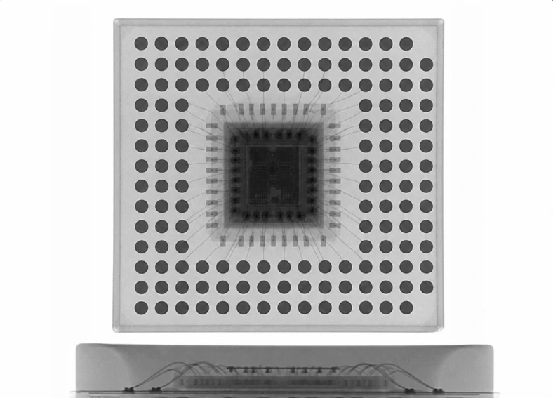
verified BGA package types or package cross-section supplied or approved
BGA describes the connection format, not a single package design
A BGA package connects to a printed circuit board through an array of solder-ball terminals on its underside. The package may use different substrate materials and internal interconnection approaches. Common package-family terms include plastic BGA, ceramic BGA, tape BGA, and flip-chip BGA, but naming conventions and construction details can vary between manufacturers and product lines.
These labels are useful starting points, not substitutes for a component datasheet or package specification. Ball pitch, body dimensions, land pattern, substrate stack-up, die configuration, and assembly constraints must be confirmed for the exact part number. Do not infer a device's internal stack or allowable process window from the “BGA” label alone.
Match the test method to the question
Different test methods provide different evidence. Visual inspection can assess accessible surfaces and placement-related conditions, but it cannot directly view solder joints hidden beneath a BGA package. Electrical tests can identify certain connection or functional failures that are covered by the test design, but they do not necessarily explain the physical cause. X-ray imaging can reveal selected internal geometric features in its projection view; overlapping structures and material contrast can limit interpretation. Computed tomography may provide additional spatial information for suitable samples and setups, but it is not automatically required or conclusive for every case.
For production acceptance, the applicable criteria come from the product requirements, customer agreements, and controlled process documentation. A test result should be described in terms of the evidence actually collected, not as a general guarantee of package quality or long-term reliability.
What can X-ray inspection contribute?
Because BGA solder connections are hidden beneath the package, X-ray inspection can support evaluation of image-visible joint geometry and some conditions such as bridging, missing connections, or void-like regions, subject to the sample, imaging setup, and acceptance criteria. Image interpretation should account for package layout and possible overlap among balls, vias, planes, and other structures.
An X-ray image does not establish electrical function, metallurgical integrity, or long-term reliability by itself. Where those questions matter, the inspection plan may need electrical or functional testing, process records, or other analysis methods. The appropriate combination depends on the failure mode and product requirements.
A practical planning checklist
Identify the exact component part number and obtain its current datasheet and package information.
Define the failure mode or engineering question before selecting a test method.
Confirm which structures are accessible to the chosen method and where interpretation may be limited.
Set acceptance criteria from controlled product and customer requirements rather than assuming a universal BGA threshold.
Record the sample, method, setup, observations, and any complementary test results needed for traceability.
BGA technology covers multiple package constructions, so sound testing begins with part-specific information and a clearly stated inspection objective. Combining methods can provide a more complete evidence set, but each result should remain within the limits of what that method can demonstrate.