How to Detect Hidden Defects in BGA Solder Joints Using X-ray Inspection
After reflow, the solder joints beneath a ball grid array (BGA) are hidden from direct view. Start with a top-down X-ray image to map the array and flag suspect joints. Then use a second view when board features overlap the area of interest or the first image leaves a joint’s shape unclear.
Check the Ball Map Before Calling a Defect
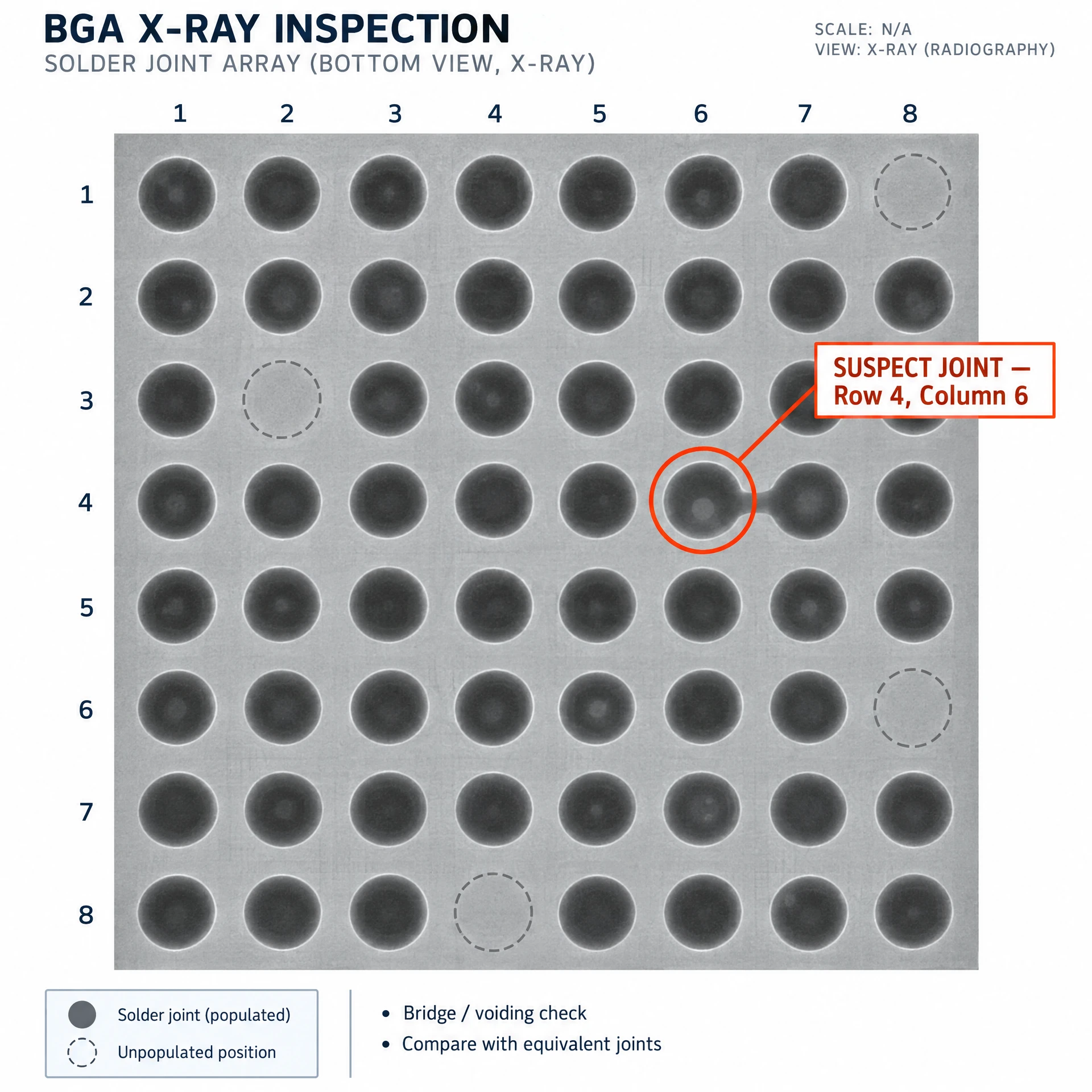
Use the package ball map to verify which positions should contain solder. Some positions are intentionally unpopulated. Compare the suspect location with equivalent joints on the same array or with a known-good board of the same design, using the same imaging setup. A solder-like connection between neighboring joint outlines may indicate a bridge. A missing outline at an expected position or a marked difference in joint shape calls for a closer look.
A void may appear as a region of lower attenuation within the solder outline. If you measure voiding on a 2D image, record it as the projected void area relative to the projected joint area. Use the product’s approved inspection criteria and keep the measurement settings consistent across boards.
Capture a Second View and Record the Evidence
An oblique view can help distinguish a suspected bridge from a trace or a feature on the opposite side of the board. Review the same joint in both images and save the views with the board ID, component reference designator, and ball coordinate. These details help another reviewer find the joint and reproduce the inspection.
Some head-in-pillow defects can retain a normal-looking outline in projection. If an interface remains ambiguous, flag the joint for follow-up. A targeted electrical test can check continuity where test access allows, while cross-sectioning can help investigate the joint interface when destructive analysis is appropriate.
For a sample evaluation with Shenzhen Wahfei Technology Co.,Ltd., share your board layout or ball map, the joint coordinates, and the defect you need to distinguish.