Automated Test Equipment (ATE): What It Covers and Where X-ray Inspection Fits
An automated test equipment (ATE) system can tell you whether a board works. It cannot tell you why a solder joint will fail in six months — because it never looks inside.
That gap is where X-ray inspection earns its place on the line. This article explains what "ATE" actually covers in 2026, what electrical test can and cannot prove, and how automated X-ray inspection (AXI) fits alongside it without duplicating it.
What automated test equipment (ATE) actually refers to
Automated test equipment (ATE) is an umbrella term for machines that test or inspect electronics automatically, with no operator judgement in the pass/fail decision. The trouble with the term is that it covers two families of equipment that share almost nothing except the word "automatic".
Semiconductor ATE tests the chip itself. A tester is combined with a wafer prober (for wafer sort) or a device handler (for final test), and the combined setup is usually called a test cell. This is the sense most people mean when they say ATE, and it is the market where Teradyne and Advantest are the long-standing leaders. What is being verified is the electrical behaviour of a die or a packaged device against its specification.
Board-level ATE tests the assembled printed circuit board. In-circuit test (ICT) uses a bed-of-nails fixture to contact every accessible node and measure component values and continuity; flying probe systems do the same job without a dedicated fixture; functional test (FCT) powers the board up and checks that it behaves as designed. Boundary scan, defined by IEEE 1149.1 (JTAG), is often layered on top to check interconnect integrity on dense boards.
There is a third group that gets folded into the same conversation: automated inspection equipment — AOI and AXI. These are frequently described as part of the ATE family because they are automatic and they gate product, but they measure physical structure rather than electrical behaviour. Keeping that distinction straight is the whole point of this article, because it explains why one does not replace the other.
The two families, side by side
The practical differences matter more than the definitions, because they determine where each system sits in the plant and who owns it.
| Aspect | Semiconductor ATE | Board-level ATE |
|---|---|---|
| Object | Die or packaged device | Assembled PCBA |
| Setup | Tester plus prober or handler | Bed-of-nails fixture, flying probes, or functional rig |
| Proves | The device meets its electrical specification | The board performs the function it was designed for |
| Blind to | Internal physical defects that have not yet changed the reading | Anything under a package, and any joint that still conducts |
What ATE cannot see, and why that gap matters
Every electrical test is a black-box measurement. Current goes in, a reading comes out, and the machine judges the reading. It has no way of knowing what the joint that produced that reading looks like.
A BGA solder ball with a large internal void will still conduct, and will still pass ICT and functional test on the day it is built. The problem appears later: less metal means less thermal and mechanical margin, so the joint cracks under thermal cycling in the field. The same logic applies to a partially bonded die attach, a wire bond that is attached but thin, and a crack that has not yet opened. None of these change a measurement today. All of them change the failure rate next year.
This is the specific job of automated X-ray inspection (AXI). It does not measure electricity at all. It images the interior of the joint and reports geometry: how much of the ball is solder, how much is void, whether the fillet actually formed, whether the wire is attached at both ends.
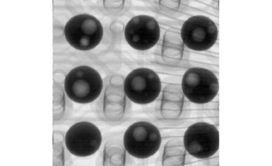
BGA solder balls under X-ray. The pale patches inside each ball are voids — the ball still conducts, so in-circuit and functional test will pass it.
AOI, AXI and ICT: who catches what
The three inspection and test stations on a modern SMT line overlap less than people assume. AOI sees surfaces, AXI sees interiors, ICT sees electrical nodes. The table below is the short version of a decision that usually takes a full line trial to settle.
| Defect | AOI | AXI | ICT |
|---|---|---|---|
| Solder bridge | Yes | Yes | Yes |
| Void inside joint | No | Yes | No |
| Joint under BGA | No | Yes | Indirect |
| Wrong part value | No | No | Yes |
| Wire bond defect | No | Yes | Indirect |
| Foreign object | Surface only | Yes | No |
How the stations divide the work
On a typical SMT line the order is: solder paste inspection after printing, AOI after reflow, AXI after AOI for boards that carry hidden joints, then ICT or functional test at the end. The logic of the sequence is simple — each station should catch what the previous one physically cannot see, not repeat it.
Placing AXI before electrical test has a practical benefit beyond detection: it catches process drift before the board reaches a fixture. If a printer is depositing too little paste, X-ray shows the trend in voids and incomplete fillets on the first boards of a run, while the electrical test will still pass them.
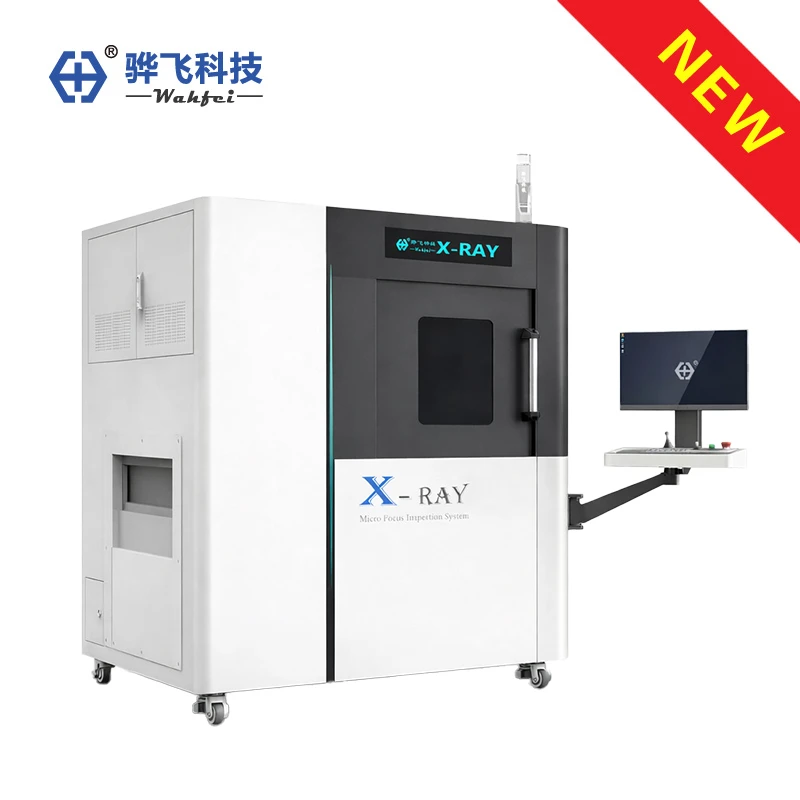
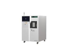
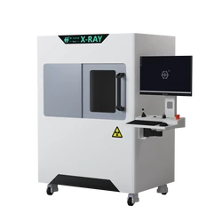
An inline X-ray platform, built to sit in the line between AOI and electrical test.
Five things to check before adding AXI to an existing line
Most integration problems are not about image quality. They are about the line around the machine.
- Cycle time. An X-ray exposure takes time. If the AXI cannot match the takt time of the line, it becomes a buffer or a sampling station, and the sampling strategy has to be decided before purchase, not after.
- Board handling. Inline systems need conveyor interface, width adjustment, and SMEMA-compatible handshaking with the neighbouring machines. An offline cabinet avoids all of this but adds a manual load step.
- Data and traceability. Decide up front how images and results reach your system: barcode-linked image files, a results database, or export into your MES. Test data from electrical ATE usually travels in STDF format; X-ray images do not, so plan the join key (serial number or panel ID) in advance.
- Fixtures and clearance. Boards with tall components or double-sided assemblies may need a specific viewing angle, and a 60° oblique view needs vertical clearance above the board. Check this against your tallest part before the machine is specified.
- Escape criteria. Define the acceptance limits for void percentage per joint type, and write them into the programme. A machine that reports numbers without agreed limits turns into a source of debate rather than a gate.
Do you need AXI, or is electrical ATE enough?
If every joint on your board is visible and your field failure rate is acceptable, electrical test plus AOI is a defensible strategy and X-ray adds cost without adding information. The calculus changes when any of the following is true:
- The board carries BGA, CSP, QFN, LGA, or flip-chip devices, so the critical joints are physically hidden.
- The product is safety-related, or the cost of a field return is far above the cost of inspection.
- You are qualifying a new process, a new paste, or a new supplier, and need to see what the process is doing rather than only whether the result conducts.
- Your customer's quality agreement specifies radiographic inspection or a void limit that must be measured and recorded.
In practice most plants end up with both, and the split is by volume: inline AXI screens the parts where a hidden joint would be catastrophic, and an offline microfocus system handles failure analysis, first-article checks, and the samples that customers send in.
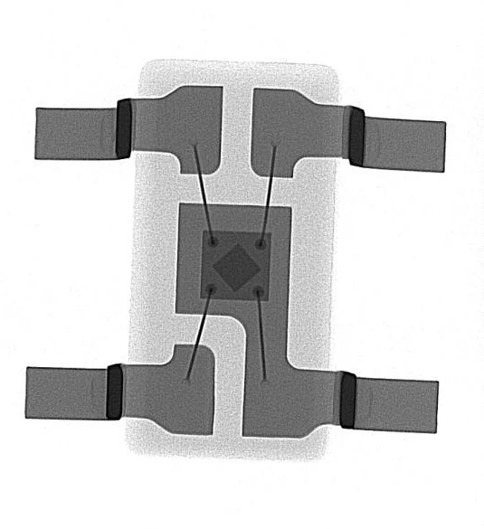
The detail an offline microfocus system is kept for: the die in the centre of a package, with bond wires running out to the lead frame. A bond made over too small an area, or a wire with a notch at the heel, still conducts on the day of build.
Frequently asked questions
Is AXI a type of ATE?
In casual usage, yes — AXI is automatic and it tests product, so it gets grouped with automated test equipment. In engineering usage the split is cleaner: ATE refers to electrical test (semiconductor testers, ICT, functional test), while AXI and AOI are automated inspection. The distinction matters when you are specifying a line, because the two measure different things and neither substitutes for the other.
Can X-ray inspection replace in-circuit test?
No. X-ray cannot measure resistance, capacitance, or whether the firmware boots. It sees geometry. A board can be geometrically perfect and electrically dead, or geometrically flawed and electrically fine. The two stations answer different questions, which is why lines that carry both still carry both.
What void percentage should we accept?
There is no universal number, and any supplier who quotes one without asking about your joint type, thermal load, and product class is guessing. Acceptable limits are usually set per joint type in your own process specification or by your customer's quality agreement, and then programmed into the inspection software as the pass/fail rule.
Does AXI slow the line down?
It can, if the machine is specified without reference to takt time. Inline systems are configured around the number of boards per minute the line produces, the region of interest on each board, and how much of the board actually needs to be imaged. Where full coverage is slower than takt, sampling plans are common; where the joint is critical, the line is often buffered instead.
Can we trial our own boards before committing?
Yes, and it is the only sensible way to specify the machine. Send boards that represent your real product — including some with known defects if you have them — and ask for the images plus the measurement report. Wahfei runs these sample inspections at no charge and returns the X-ray images with an evaluation report, so the configuration decision is based on your joints rather than on a demonstration board.
About Wahfei Technology
Shenzhen Wahfei Technology Co.,Ltd. builds the X-ray inspection side of this stack: offline microfocus X-ray systems, inline automated X-ray inspection (AXI) systems, and industrial 3D CT systems, all running on the company's self-developed X-Mind imaging software. Wahfei does not manufacture electrical ATE; the systems are designed to sit alongside it, share the same board handling conventions, and report results that can be joined to your existing traceability data.
The company was founded in 2018, is based in Shenzhen, China, operates under an ISO 9001 quality system with CE and FDA related certifications for export markets, and has systems installed in more than 20 countries, including the United States, France, Malaysia, Vietnam, and Turkey.
If you are deciding where X-ray fits in a line that already has electrical test, send us a board and a description of the failure you are chasing. The answer usually becomes obvious once the joint is on screen.
WhatsApp / Phone: +86 189 0297 8624
Email: szwahfei@gmail.com
Website: https://www.wahfeixray.com/